Installation and User Manual for Toba MEMU-7 digital boat gauges unit.
- Toba
- Nov 29, 2023
- 23 min read
Updated: Feb 15, 2024
**We highly recommends you read this manual before installing the unit.**
Table of contents
1. Introduction and Overview
2. Specifications / What’s in the box
3. Installation best practices
4. Mounting instructions
5. Sensors
6. Wiring
7. Setup
7.1. Tachometer
7.1.1 Coil Negative
7.1.2 Coil on Plug/Injector Logic
7.1.3 Charging Coil
7.1.4 Variable Reluctor
7.1.5 Digital Sensor
7.1.6 CDI Ignition
7.2. GPS Speed
7.3. Coolant temperature
7.4. Oil Pressure
7.5. Fuel level
7.6. System Voltage
7.7. Rudder angle
7.8. Generic gauges 1, 2 and 3
7.9. Peizo alarm
7.10. Wiring diagram
7.11. Tachometer Pulses Per Revolution Data Table
1. INTRODUCTION & OVERVIEW
The Toba MEMU-7 unit is a direct replacement for standard analogue gauges for your boat’s helm. The unit reads standard resistance style single or two-wire sensors to measure engine states applicable to temperature, oil pressure, rudder position and fuel level. Battery voltage is displayed from its power source, boat speed via GPS, and engine speed by a number of means applicable to most marine engines. The unit includes three generic additional gauges that read the same resistance type sensor which you, the user, can configure to display whichever state you may choose e.g., a tank level, another temperature/pressure sensor etc.
The MEMU-7 digital boat gauges unit is designed to be a universal robust solution to an older approach to engine/boat monitoring and is configurable to give the user complete control over how it works, what it displays and when it alarms, offering an enhanced experience over traditional gauges more like modern engine user interfaces.
With both a visual and audible alarm provided (the alarming gauge glows red and, a buzzer alarm provided with the unit either buzzes constantly or intermittently as is preferred by you), the unit is a very good way to ensure that your systems are running as intended and if not, you are alerted to an issue well before damage is done.
We recommend that prior to attempting setup, the unit is fully installed and properly terminated.
2. SPECIFICATIONS
Screen – LCD 7” TFT
800x3(RGB)x480
LOCA bonded
1400 Nits (cd/m2) brightness
Unit – 10 to 30v input voltage
Sensor input range of 0 to 5000 Ohms or 5000 to 0 Ohms
Power consumption at full brightness – 0.4A @ 24v (0.2A @12v)
Water resistant (No IP rating at this time)
Case – UV stable ABS Plastic
What’s in the box - 1 x MEMU-7 unit
1 x MEMU-7 sun cover
1 x MEMU-7 mounting bracket
2 x M6 Thumb screws
2 x M6 Stainless Steel threaded rods
2 x M6 Thumb nuts
1 x GPS antenna
1 x Dual tone piezo alarm buzzer (90Db)
1 x Paper cutting template (printed on the lid of the box)
1 x Foam gasket for dashboard sealing (only in flush mounted applications)
1 x red inline fuse, 1 x white inline fuse
3. INSTALLATION BEST PRACTICES
The MEMU-7 was designed to be a water-resistant unit for use on boats where the helm sees water and sun often though intermittently.
***We highly recommend that when the unit is not in use the sun cover is placed on as over time the screen may become sun damaged if not covered when not in use. We do not recommend pressure washing.
Ideally the unit is best mounted so that the viewing angle is relatively squarely in front of your eyes, however, the screens are quite viewable from a more acute angle. We recommend you test the viewing angle you intend to use in your boat before you confirm its installation position.
The unit requires a clean power source which is switched by your ignition key, we recommend that the wiring to the key and the connections from the engine are pulled apart and checked for integrity, the marine environment can be harsh and corrosion or bad connections will interfere with how your MEMU-7 operates.
***Most importantly, your MEMU-7 uses a battery ground return system to measure the sensors on your engine/s therefore the integrity of the ground connections must be checked and be observed to be in excellent condition. Ensure that the terminations on the ground cables from the engine to your battery, battery to your helm and helm to your unit are ideally crimped and soldered. Poor connections will ensure that your unit does not operate correctly and will result in incorrect sensor readings.
***We recommend that if you are replacing working analogue gauges, take notes on what cooling water temperatures, oil pressures or any other metric you may read with this unit e.g. gearbox temperature or engine boost pressure at cruising speed. This can be handy information to know when configuring the MEMU-7 unit for comparative purposes.
4. MOUNTING
The unit is suitable for boats with open helms and is UV stable, shade is preferable as is an enclosed mounting position however the unit is designed to tolerate a position on an open helm or bridge.
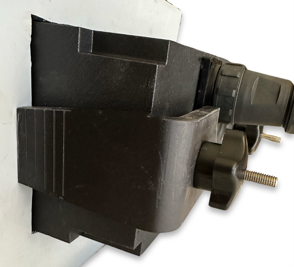
Mount the unit with either the bracket provided similar to many popular screens or flush mount it into the dash as you see fit. A cutting template is printed on the inside of the MEMU-7 cardboard box which offers an easy way to setup and mark the flush mount hole that needs to be precisely cut into your helm.
The bracket mounted option should use all three screw holes with ideally 8 gauge or 10 gauge screws or, bolted through if that is achievable.
The flush mounted option has been made simple by merely measuring the thickness of your dash/helm. There are lines embossed in the side of the bracket marked “A” to “F”, these lines are to allow for easy cutting of the bracket and when cut, it is used as a rear clamp to hold the unit into the helm dash securely. Each line is a 5mm increment which relates to the thickness of your dash i.e. if your dash is 15mm thick, cut both sides along the line marked “C”. If your dash is 5mm thick, cut along the line marked “A”. See below.

Use the threaded M6 rod and thread both rods into the nut inserts into the back of the unit.
This mounting method is made easier for those helms that are not easily accessible, the thumb nuts can be threaded and tightened one handed, they should be firm but over tightened.
5. SENSORS
MEMU-7 will work with any one or two wire sensor which delivers a varied resistance depending on its changing state be it pressure, temperature or level. If the sensors you have in your boat were working with your old analogue gauges, they will work with this unit. Otherwise, we encourage the use of quality OEM sensors. However, many aftermarket sensors are just fine so if what you have does not work, use another quality sensor to get things working. Bear in mind, one wire sensors have a battery ground return path through the engine block, typically two wire sensors do not. If using a two wire sensor (e.g. a GM coolant sensor or Caterpillar coolant sensor) one of the two wires needs to be grounded to the engine block for its ground return path or wired to the unit’s BATT NEG. Often these engines have independent ground wires running up to the dash, all sensor grounds can be grounded at the unit with its battery NEG wire in that case.
The MEMU-7 will accept any resistance sensor between 0 OHMS and 5000 OHMS. It can deal with higher resistances however, lower are preferred.
If you wish to change sensors or renew them for piece of mind, our website will offer a stock of generic sensors which will work, along with adapters to allow for easy fitment to differing thread types.
6. WIRING
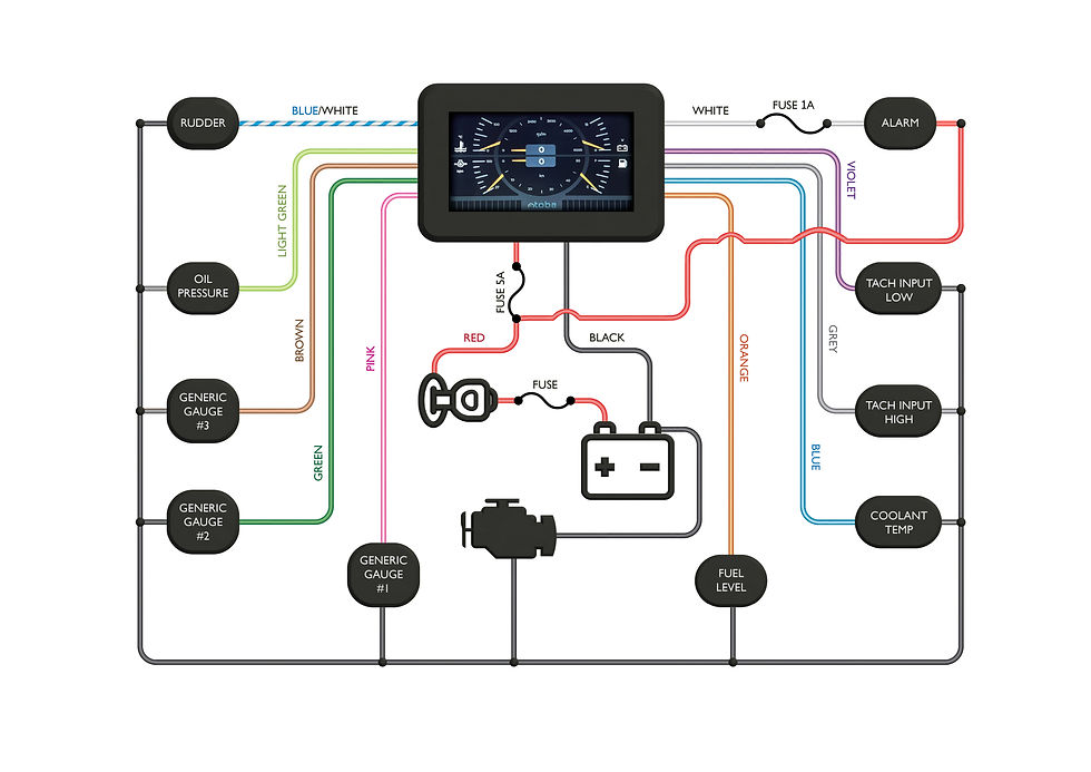
The wiring of the MEMU-7 digital gauges is simplistic, it requires a switched power between 10 and 30v DC, a good battery ground and good connections to each sensor. We have included a full-page wiring diagram at the end of this document.
It is imperative that the unit’s ground and the ground returns for the sensors are at the same electrical potential, this requires excellent connections between the battery, unit and engine block. Sometimes a connection can look ok from the outside however, the crimped terminal can become corroded and high resistance under the crimp. We recommend crimping new terminals on all those connections and soldering them. Solder is a great way to ensure corrosion is kept at bay on terminations especially on the engine block. Where the ground cable is terminated to the engine block, ensure it is removed, re-terminated and cleaned back to bare metal before reinstalling it. If the wire you are crimping/soldering to appears black in colour rather than a nice clean copper colour, cut the wire back until you get nice clean copper or, simply replace the entire wire.
The unit comes with two inline fuses, a red and a white. The RED (5 AMP) is used to fuse the Batt+ from your ignition key. This does not protect the unit itself, the unit has inbuilt electronic protections. This fuse is to protect the cable powering your unit from your ignition key. Therefore, ensure that the fuse is placed inline on this power wire right at the ignition key, not near the unit or halfway down. If this wire were to short circuit between the key and the unit, the fuse will blow and not cause risk or harm to your boat and those aboard. The WHITE (1 AMP) must always be placed on the WHITE wire from your unit which is a switched BATT NEG (GROUND) wire to operate your piezo alarm. If the alarm output wire is shorted to BATT + the unit may be damaged so placing this fuse right near the unit is important to protect the unit.
Your existing wiring from the analogue gauges you are replacing will be sufficient, there is only a very small amount of current being passed through them in fact, less than 10mA so there is generally no need to rewire all the sensor connections in most cases, the old analogue wiring is more than sufficient as long as it is in good condition and well terminated.
Be mindful that at times sensors have spade terminals or ring terminals, sometimes plugs. Spades and rings can become loose so ensure that they are well connected, if in doubt, replace them and solder the crimp.
When connecting to your existing wiring, we do not encourage crimp terminals, solder and heat shrink is best and ideally, glue lined heat shrink offers best water proofing over time.
7. SETUP
To enter “setup” mode of any gauge, simply press and hold anywhere on the gauge and the unit will go into the setup page for that gauge. Once the values are changed, they are automatically saved, there is no “enter” button or “save” button, the unit will commit to memory whatever values you enter. For all alarm settings, any value entered will be seen by the unit and counted, if you do not wish the unit to alarm, simply leave that alarm value blank, the unit will ignore that value.
To go into general “settings”, press and hold the “Toba” logo at the bottom of the screen, this will take you into general settings.
In general settings there are three choices, “Display Brightness”, “Software” and “Other”. The brightness slide bar will adjust the screen brightness output to your liking and is easily accessed at night.
The software tab allows you to connect to the internet via WIFI and check for a firmware update. Simply click the refresh button to search for a nearby WIFI network and enter the access password for that network, once connected click “Update software”. The unit will automatically connect then check that it has the latest version of the firmware, if not it will download and install the latest version. Once it is complete, the unit will power cycle itself and the update is complete.
The “Other” tab simply displays your current GPS location in Longitude and Latitude, current speed and Satellite count i.e. the number of satellites the unit is currently tracking for its GPS data.
Below the GPS information, there are three choices of “demo modes” you can run if the need or desire arises, rudder, speed and sensors. They can either be used one at a time or all together, the unit will randomly actuate those gauges for display purposes only.
7.1 Tachometer gauge.
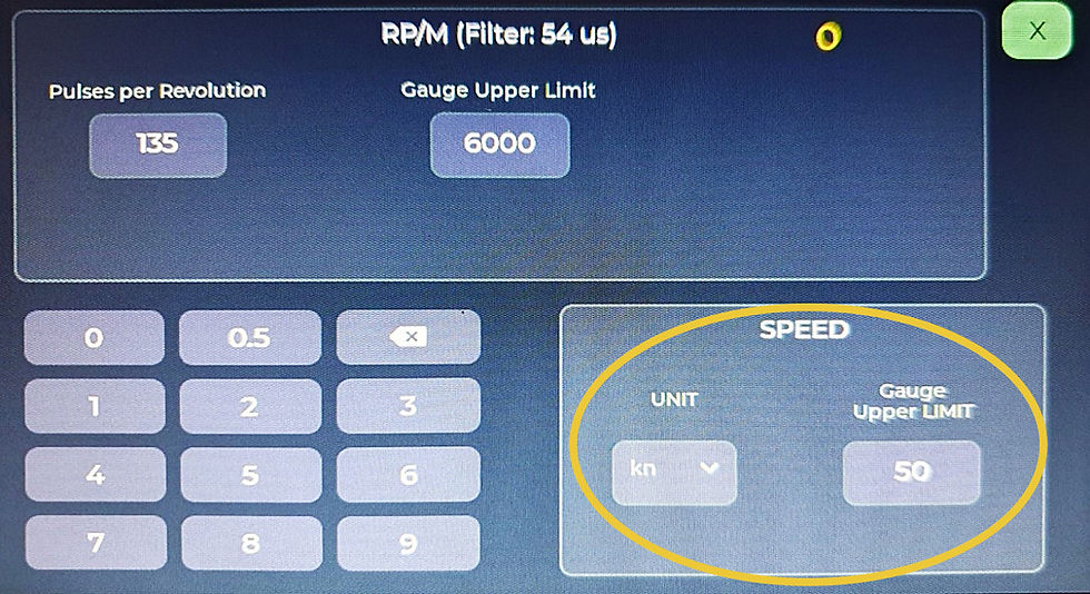
Before setting up the tachometer gauge, set your gauge limits in that screen by pressing and holding the tachometer gauge taking you into its config page. Set the gauge’s upper limit which we always recommend being 200 or 300 RPM above the engine’s specified red line speed. In this page you can also set the speed gauge’s upper limit and unit of measurement i.e. knots/m/h or km/h.
Pulses per revolution are explained below as a critical setting for an accurate tachometer.
The tachometer input is designed to accept and condition a range of common place tacho inputs for ease of connection to almost any engine platform. The unit is equipped with a “High” and a “Low” tachometer input and in any installation only one of those inputs will be used. Which one is selected is dependent on the source of your tachometer input signal. Essentially, the signal voltage of the tachometer input source decides whether high or low is used. Typically, the high input is used for tachometer signal voltages of over 80 volts the low input, under 80 volts. Each of the input guidelines below will help you determine what input is required for your installation.
The MEMU-7 unit determines engine speed by calculating the number of pulses or voltage spikes it sees for every revolution of the engine so no matter where your signal comes from, that is the most relevant setting to determine and in most cases it is very simple. Even if the number of pulses per revolution is elusive to you, trying a few choices quite quickly finds the right number as you should be aware of your standard idle speed before you embark on this installation, entering the correct number will see the correct speed at idle and you are good to go. In most cases we can provide you with the correct number to use. Some engines may have quite unusual pulse per revolution, particularly where a sensor is used where flywheel gear teeth are the triggering signal. Please note, if setting up the tachometer is elusive, most servicemen have handheld tachometers that can determine the precise speed of an engine at idle, you can use one to tune the unit to the precise pulses per revolution number which makes it accurate, this may at time mean that the number is a decimal e.g. 58.5 PPR.
Before we detail the tach inputs and how they work it is worth noting that many engines have a dedicated tacho output from an ECU or in the harness which will work fine as it will be a digital pulse. Determining precisely how many pulses per revolution can be more difficult, though trial and error is best as a starting point.
***Please note, on any connection using the “Low” input, ensure that you do not run the cable, if possible, near any high voltage/current wiring. This at times can induce a small voltage in your tach signal wire and cause an issue with the signal or cause misfire in your engine depending on where you have made the connection.
The MEMU-7 unit will accept the following tacho input signals:
7.1.1 Coil negative.
For petrol (gasoline) engines with a single ignition coil. The signal comes from the same connection to the coil most tachometer gauges use. Good for inboard and stern drive applications which are generally pre-fuel injection. This input sees more than 100 volts, so it is always connected to the “High” tachometer input. Its configuration in the tachometer settings is determined by the number of pulses the coil negative gives while running. On a four-cylinder four stroke engine, the “pulses per revolution” is set to “2” as in every revolution of the engine only two cylinders fire; in a 6 cylinder the setting is “3”, and in an eight cylinder the setting is “4”.
The connection for this input is simple: there are two connections on the coil, one being +12v/24V from your ignition key, and the other is battery negative or ground. The connection for this input is made to the battery negative or ground on the ignition coil.
**Connect Tach input HIGH to this terminal.

7.1.2 Coil on plug / fuel injector logic.
For fuel injected petrol (gasoline) engines. This signal is taken from the signal or control wire which turns the ignition coil or fuel injector on and off. (Where this is done once per firing sequence). This signal is used where the ignition coil and fuel injector are typically on each cylinder so in those cases the “pulses per revolution” setting is 0.5 on a four-stroke fuel injected engine. This is due to the fact that any one cylinder only fires every second revolution. However, there may be instances where injectors are batched fired or where coils are used in wasted spark. If injectors are batched fired, they may be fired once per revolution. In those cases, change the settings of “pulse per revolution” as is required to get the correct idle speed showing on your screen (a few attempts will likely find this easily). In the case of wasted spark, the “pulses per revolution” will be doubled to “1” in the settings as these coils are being fired twice as much as a coil on plug installation i.e., on every engine revolution.
The voltages seen in most applications is 5 Volts or 12/24 Volts so this input will be connected to the “Low” tachometer input. Please note, this is not applicable to common rail diesel injectors, they operate at much higher voltages and can at times be fired multiple times per cylinder firing sequence. If attempting to connect to a common rail diesel injector logic circuit, it would be connected to the “Low” tachometer input on the provision that the injector voltage does not exceed 80V, otherwise connect to “High”. Multiple firing of diesel injectors (in one cycle) may or may not work, it is therefore preferential to obtain a signal from a crank sensor or mount another sensor to read the ring gear (such as the sine wave reluctor sensor in our online store.)
The connection for this input is simple, whether an injector is used or an ignition coil, they employ one power wire (battery voltage turned on by ignition key), one battery negative or ground, and one logic or control wire. A test probe will identify which of these are power and ground, the third will be the logic or signal wire which switched the injector/coil on and off; connect to that signal wire.

***Digitally triggered coil packs typically have a +12v supply, a Batt Ground (NEG) and a third wire which switches the coil on and off, connect to that wire to get a clean digital signal and connect to the “Low” input.
7.1.3 Charging coil connection.
Generally, for outboards, jet skis and many marine engines which use an AC generating stator being either single phase or three phase for its onboard electrical charging. This is used by many manufacturers as a standard tachometer input source, and it produces an AC waveform whereby voltages loosely vary from 15V at idle to 60V at full engine speed. The number of “pulses per revolution” in this instance depends on the number of poles in the charging arrangement. This information can be looked up for most popular engines (see our table in this manual below or on our website) or it can be determined by trial and error when setting up the input. Typically, most systems have 4, 6 or 12 poles, some may have 18. In every situation the correct setting for “pulses per revolution” is half the number of poles on the flywheel. E.g., if you have 12 poles set the pulses per revolution value to 6. The number of poles can be found also by using a metal screwdriver or the like to work around the inside of the flywheel which turns around and over the stator. The magnets in the flywheel can be counted by slowly running the metal object around and feeling for each pole. However, it is generally much easier to simply try all the common numbers i.e. 2, 3, 6 and 9 to find you correct idle speed and therefore the correct setting.
The connection for this input is simple, on most engines, the phase wiring if three phase will be three wires of the same colour coming out of the stator and going to an ECU or a regulator/rectifier. Wire your tachometer input to any one of these three wires. Some engines with three phase stators have six wires; wire to any one of those to get a good signal. Single phase stators typically have two wires of the same colour coming out of the stator and going to an ECU or a regulator/rectifier. Wire to any one of these wires to get a good signal. Wiring to the stator windings will not damage your engine, almost all OEM’s use this as an output for their tachometers at the helm.
The charging phase input is wired to the “low” input.
7.1.4 Variable reluctor sensor
Many crank sensors are variable reluctor and many diesels use the same sensor for an accurate tacho signal. They are a two-wire sensor which produce a small AC voltage when passed closely to a ferrous metal e.g., a gear toothed wheel. To wire to this sensor, connect one wire from the sensor to engine ground (battery negative) and the other to the “Low” tachometer input on the unit. We have provided a number of references below for the pulses per revolution settings for many common marine diesels, if however, it is difficult to find the setting, you may seek to count the number of teeth or segments on the trigger wheel that the sensor is reading. The pulse per revolution setting is exactly half the number of teeth/trigger wheel segments. (i.e., where there are 147 teeth on the trigger wheel, the setting would be 73.5).
***Please note, we do not recommend this unit share a crank trigger output with an engine ECU, there are electrical noise concerns which can interrupt an electronic engine’s operation. If need be, mount another crank sensor so the trigger signal is not shared. Both sensors can share a wheel but not a signal.

(Polarity is not important with this type of sensor, it can be wired either way.)
7.1.5 Digital sensor
These sensors are less common on marine engines however can be read without issue. These are three wire sensors which use a positive voltage (can be battery voltage or a regulated 5V from an ECU in many cases) a ground (battery negative) and a signal wire. Connect to the signal wire from the sensor to the “Low” tachometer input which will provide a square wave with an amplitude of the supply voltage. You can use a generic 12/24v digital sensor and simply supply the sensor with ignition voltage to get a good signal back to your unit. This sensor cannot be shared with an engine ECU.

(Wire colours vary from sensor to sensor, see OEM references for sensor pinouts.)
7.1.6 CDI Ignition
The MEMU-7 unit is capable of using very high voltages for a tach signal. The CDI ignition input is just that, and when running, the voltages from the CDI ignition to the engine’s ignition coil are in the hundreds of volts. This connection is essentially taken from the wire that turns a coil pack on and off from the CDI ignition unit. That signal can only be wired to the “High” tach input on the unit.
***Please note, if a CDI switching wire is connected to the “Low” input, this voltage will cause damage to the unit which is not covered by warranty as it is an error in installation.
***Please do not attempt to make this connection to a running engine for risk of electrical shock.
***Some CDI ignitions look similar to Transistorised Coil Ignition systems, it is important to determine which of them you have, a CDI system is connected to the “high” input, a TCI system is connected to the “low” input.
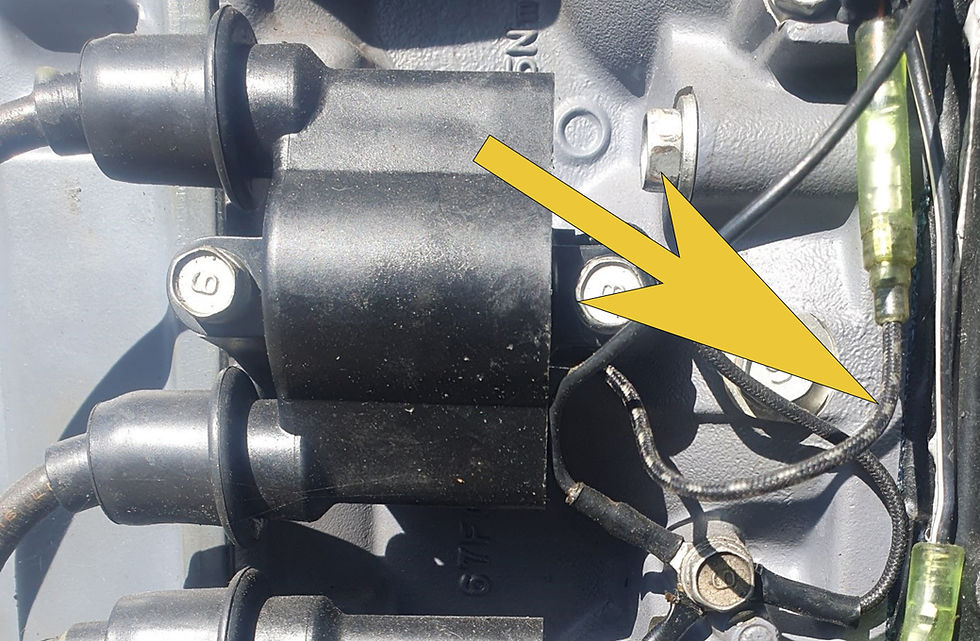
***Connect the unit to the wire indicated by an arrow above, the other is a ground wire for the coil.
7.2 GPS Speed gauge.
The speed settings are detailed above and are set in the same config page as the tachometer. They are merely a choice of units of measurement and the gauge’s upper limit. It is recommended to set your upper speed limit to a number just above the boat’s maximum possible speed.
Included with the MEMU-7 unit is a GPS antenna. Though the GPS chip itself does have an antenna, it is internal to the unit and does not always track satellites well, especially if inside an enclosed bridge or other obstruction. We encourage that even if it appears to work well without the antenna, connect it anyway and mount it somewhere where it can see sky. The antennas are waterproof and UV stable so on the roof/outside the boat is just fine.
7.3 Coolant temperature gauge.
Coolant temperature is read and displayed from the sensor as a circuit resistance. When connected this is displayed by the unit in the config page for that gauge. When the circuit is not connected, the value is shown as “N/C” meaning, “Not Connected”. See below.
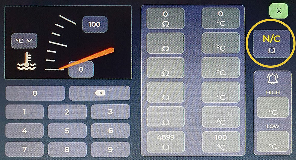
To configure to this sensor, you need to input resistance measurements of the sensor and assign each of those measurements to each of the six resistance values. The reason for this is because the unit uses those six points to extrapolate the non-linear curve that most sensors of this type have to be able to provide a reading. See below example illustration of coolant temperature non-linear curve whereby we have illustrated the six points required to obtain good readings. (Six points in red/blue crosses.)
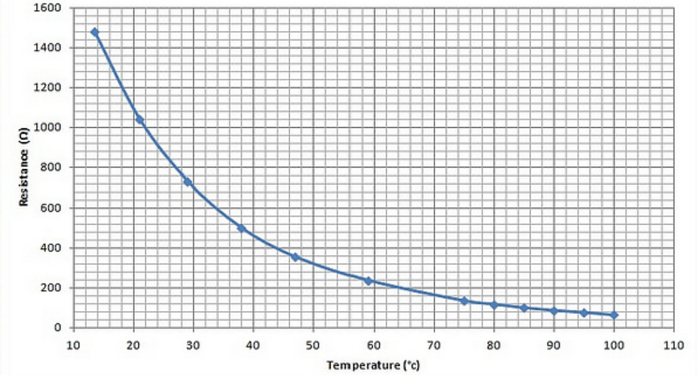
You will note that the upper and lower plotted points are in red, they are important as to set the overall ‘goal posts’ for the gauge operation. As an example, if your engine has a thermostat temperature of 80C (176F), then the gauge limits of 20C (68F) to 110C (230F) would be ideal upper and lower settings when configuring the unit.
The six points you require can be obtained by a number of ways; we have that data on our website which we update regularly. You may be able to perform a search online for the part number of your specific sensor and obtain six points that way. If neither are successful, you can remove the sensor and place it in a pot on a stove. As it heats up record a number of points from which you can chose six evenly spaced points to configure your unit. The sensors we supply have the applicable data on our website, so configuration is simple and a one-time necessity.
Don’t forget to set your alarms, also not forgetting to wire the piezo alarm buzzer. We recommend it be placed under the dashboard away from water, they are not waterproof. The temperature gauge has both a low and high alarm, we recommend use of the high alarm, only. Set the temperature in which best suits you and your engine for the alarming state. If, for example, your engine thermostat is 82C (180F) and your engine/s typically stay at that temperature (as they should if operating correctly) then we recommend setting the alarm to approximately 10 degrees warmer. If an event occurs whereby your engine suffers a water deprivation or cooling blockage, you want the alarm being triggered well before engine damage is done saving you an enormous and expensive headache.
7.4 Oil Pressure gauge.
Oil pressure is read from the sensor as a circuit resistance, the same way the unit reads all other sensors. When connected this is displayed by the unit in the config page for that gauge. When the circuit is not connected, the value is shown as “N/C” meaning, “Not Connected” (see below).

To configure to this sensor, you need to input resistance measurements of the sensor and assign each of the measurements to each of the six resistance values. The reason for this is because the unit uses those six points to extrapolate the non-linear curve that most sensors of this type have to be able to provide a reading. See below example illustration of coolant temperature non-linear curve whereby we have illustrated the six points required to obtain good readings. (Six points in red/blue crosses.)
Temp (C)

Resistance in Ohms (Ω)
You will note similarly to coolant temperature that the upper and lower plotted points are in red, they are important as to set the overall ‘goal posts’ for the gauge operation. As an example, if your engine runs at cruising speed with an engine oil pressure of 413kpa (60 psi), then the gauge limits of 0 to 850kpa (120 psi) would be ideal upper and lower settings when configuring the unit.
The six points you require can be obtained by a number of ways; we have that data on our website which we update regularly. You may be able to perform a search online for the part number of your specific sensor and obtain six points that way. If neither are successful, you can remove the sensor and apply compressed air via an air regulator and similarly to the coolant temperature sensor, measure a number of points between your upper and lower limits, chose six evenly spaced points to configure your unit. The sensors we supply have the applicable data on our website, so configuration is simple and a one-time necessity.
Don’t forget to set your alarms. Again, we recommend it be placed under the dashboard away from water, they are not waterproof. The oil pressure gauge has both a low and high alarm, we recommend use of both. When a low alarm is set, your unit when switched on with the ignition key will sound the alarm and the oil pressure gauge red, once the engine is running, oil pressure is achieved the alarm state turns off. This is a good test every time you start your engine, and we recommend the lower limit be set to something well under your idle pressure, and something above zero, e.g. 70kpa (10psi) as most engines will easily make more pressure at idle speed. We recommend setting the high alarm at a reasonable amount over its high engine speed pressure, just be sure to apply a reasonable margin.
7.5 Fuel level gauge.
Fuel level is measured the same way as the other sensors and is very simple to setup, we encourage you to remove your fuel sender if possible and hold the sensor next to the tank with the sensor connected to the unit to obtain readings which corelate to ¼, ½, ¾ and full tank. Some tanks are shaped oddly, and this might be the best way to ensure that you get the best readings from your level sensor.
Alternatively, you can leave the sensor in the tank, when the tank is dead empty or close to it, begin filling the tank and if you know how much fuel it holds when empty, you can divide that by four quarters and achieve the same outcome by assigning resistances as a division of the overall resistance gap of the level sensor (e.g. many level sensors are 240 to 33 Ohms, 240 Ohms would be dead empty, 188 Ohms would be 3/4 , 136 Ohms would be ½ and 85 Ohms would be ¼). The fuel gauge operates the same as the others, the circuit resistance is displayed in the circled box and if no sensor is connected it shows as “N/C”.
See below.
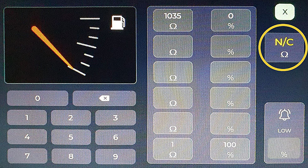
It is always best as is with the other gauges, to ensure that the upper and lower limits are set properly, in this case dead full and dead empty. That way you will never get stuck misunderstanding how much fuel you have onboard. You can also decide if you want to run ‘reserve’ in that, you can calibrate the unit such that the gauge reads as empty when you have a known quantity remaining in your tank, it is entirely up to you how you wish to do this and how much ‘reserve’ you prefer to run. In the example above you might make the “empty” value 210 Ohms which when reading as dead empty would mean there was some reserve fuel in your tank.
The fuel gauge has only a lower limit, likely quite handy if you get reminded of how little fuel you have, depending on where you are at the time, you may choose to slow down and reduce your fuel burn or find fuel soon.
7.6 System Voltage gauge.
The voltage gauge has self-adjusting gauge limits, the upper and lower gauge limits cannot be manually set. The unit will detect the voltage and set the limits to suit either a 12v or 24v system. When the unit detects a battery voltage of 15v or more, it will scale the voltage gauge for a 24v system automatically.
The lower alarm limit is settable and quite handy if your engine stops charging, or you have an electrical issue. We recommend that for a 12v system a lower alarm limit of 11.9v and for a 24v system 23.8v is a reasonable place to alarm the charging system though, set these as you prefer.
7.7 Rudder angle gauge.
The rudder angle gauge reads one sensor and one sensor only. In the case of twin-engine boats where you wish to have the rudder angle displayed on both screens, you will either need to mount two sensors or, purchase a dual output sensor which effectively two sensors in the one case. We carry these in our online store.
**** In the future we predict that we will release a firmware update which will allow the units to share this data over WIFI which will also be helpful where boats have an upper and lower helm station.
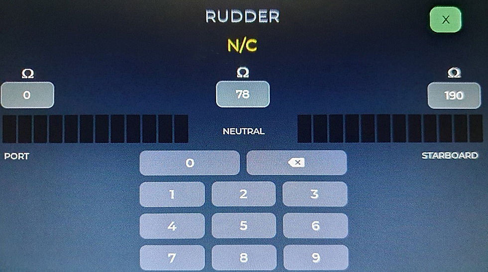
The rudder angle gauge is very simple to setup. With the sensor connected to the unit, simply turn the wheel all the way to port and read the resistance of the sensor in the config page, then enter that resistance, turn all the way to starboard and do the same. We have added a third resistance setting for when the vessel is tracking dead straight. We like to be able to ensure that when tracking straight, the rudder angle gauge is showing that. So once setup is complete, the next time you are at sea, track a dead straight line while underway, go into the rudder indicator setup page, read the middle resistance and enter that in the middle setting. When tracking straight the unit will show one bar of read and one of green.
In the below example, the circuit is reading as “not connected”, the port setting is 0 Ohms, centre 78 Ohms and starboard is set as 190 Ohms.
7.8 Generic gauges 1, 2 and 3.
All three generic gauges are accessed by swiping the screen left or right. They are configured the very same way as the temperature and oil pressure or in fact fuel if you chose to use them for tank levels. They are all alarmable the same way.

In these gauges you can select its use between degrees C, degrees F, psi, kpa and %. You can name them and set the gauge limits the same as the other gauges. See below.

You may wish to use these for water tanks levels, black water tanks levels, boost pressure, sea water pressure, oil temperature, air intake temperature or in fact anything which you can find a compatible sensor for. We stock some sensors and will be adding to that range on an ongoing basis.
7.9 Peizo alarm.
The piezo alarm supplied with the unit is a 12/24v dual tone alarm. The red wire on the alarm is always connected to the same POSITIVE (RED wire) power supply as the unit.
To achieve an intermittent alarm, connect only the YELLOW wire on the alarm to the fused alarm output on the unit, which is the WHITE wire.
To achieve a solid alarm sound, connect only the BLACK wire on the alarm to the fused alarm output on the unit, which is the WHITE wire.
Mount the alarm somewhere under the dashboard out of water or moisture, it is not waterproof like most piezo alarms. It is quite loud so under the dash would be ideal.
7.10 Wiring Diagram - click HERE to download.
7.11 Tachometer setting data - click HERE to download.

Comments